Projects/ Metallurgy
JSC "Vasilkovsky Mining and Concentrating Plant " Automated control System for Concentrating Plant technological processes
Customer JSC Kazzink Ust-Kamenogorsk
1 THE PURPOSES OF THE AUTOMATION SYSTEM ELABORATION
The main purpose of the automated control system is to increase functioning effectiveness at the concentration plant of Vasilkovsky Mining and Concentration Complex owing to the following factors:
- Optimization of the processes control based on the high-quality measurements, physicochemical and mathematical models of these technological processes.
- Applying up-to-date means and automation systems.
- Integrating the systems and the control loops by means of separate sets and technological processes.
In the frame of the elaborated automation and control system the following problems have been solved:
- The control loops of technological processes parameters in the complex auriferous ores processing and of the analytical verification points and of the original stock physical characteristics measurements, of intermediate and final products of the technological repartitions;
- Local control systems integration developed on the base of the different software and technical platforms which are received from different equipment suppliers and manufacturers has been made as the uniform system based on multilevel distributed data networks;
- Effective automation control has been developed to provide technological ore processing pilot operation.
2 AUTOMATION OBJECTS LIST
The automation system includes automated work control of the following production units at the concentration plant:
- Mother conveyer and open crushed ore;
- Intermediate and small crushing unit;
- Fine crushing unit;
- Grinding unit;
- Gravity and float concentrates grinding unit;
- Floatation unit;
- Concoction unit;
- Hydrometallurgy unit;
- Desorption and actuation unit;
- Tailing unit
There is a possibility to enlarge the automation objects owing to the communication means and software platforms.
AUTOMATED CONTROL ELEMENTS
3.1 General provisions
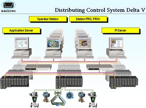
The concentration plant control is realized by means of the unified integrated technological process control system. Distributing Control System Architecture (DCS).
3.2 Technological Process Control System
Technological process control system is applied as the unified DCS in the whole concentration plant automation scheme. This system provides manual and automatic control and processes different alarm signals which can possibly come from the technological process and the equipment.
3.3 DCS Structure
DCS structure is developed on the base of Emerson Delta V system. The system is based on the computers network and the modules. It applies the systems, networks and industry-specific standard operation protocols. The system provides the interaction with range of devices on the standard driver package.
The system includes the support means to connect different computer network according to the standard soft and hardware.
The system supports the scalable structure expandability. Additional controllers and operational interface modules are possible to integrate into the open control system without any additional working stations. Data base size spread-out is supported without any additional data bases or working stations.
3.4 Local control Systems
Particular sites and equipment elements apply definite program logic controllers (PLC) or other systems to control the technological process. For instance, gravity concentrators Knelson are supplied with the local control system.
DCS supports the communication with the PLC and control systems to give the information concerning monitoring and alarm signals to the screen of DCS operators. PLC and other control system information is given to the DCS operator stations simultaneously with the information received from DCS controllers.
3.5. Communication networks DCS
Structure of hierarchical network to achieve definite functional characteristics and operation scope is applied in DCS. The communicational lines of the lower level are separated from the other communication networks at the plant. The system provides controlled interconnection with the local network Ethernet at the upper levels.
Basic remote communications between DCS equipment elements are fiber optic.
3.6 Operator Station Objects
The central operator station is supplied with the control panel, computers, keyboards, display devices system and printers for reports.
4 МOTHER CONVEYER AND ORE CRUSHING UNIT
4.1 INTERMEDIATE AND SMALL CRUSHING CONTROL
Mother conveyer is determined to carry ore with the grain size 350 mm from the open pit to the crushed ore stock. The open pit length is about 1500 m.
See Table4.1 for the main control functions.
Table 4.1
| № |
Control Object |
The parameter under control |
| 1 |
Bins |
Level control |
| 2 |
Conveyers |
Conveyer belt over-tail control
Belt slip control
Belt break control
Loading point piling control
Blockout control
Remote on/off control
Work/Stop control |
| 3 |
Transporter metal detecting |
Metal signaling
Transporter blockout |
| 4 |
Grinding mills |
- Temperature control
- Pressure and oil flow control
- Current control in the motor feed circuit
4. Piling loading point |
| 5 |
Transporter |
Ore to process recording
Conveyer belt over-tail control
Belt slip control
Belt break control
Loading point piling control
Blockout system (safety system)
Remote on/off control
Work/Stop control |
THE MAIN CRUSHING CONTROL
The purpose of crushing process automation is to regulate grain-size composition and to feed the pulp with the given density to floatation with the exhausts of hydro cyclone units.
See Table 5.1 for control loops.
Table 5.1
| № |
Control Object |
The parameter under control |
| 1 |
Mill loading |
- Head ore loading regulation
|
| 2 |
Mill |
- Mills bearings temperature
- Oil pressure at the oil plant
- Oil flow
- Correction of the ore load according to electric motor drive active power
- Ore to process recording
- On/ Stop motor control
- Motor drive technical state diagnostic operations
- Water feed to the mill mouth regulation
- Automatic balls dosing
|
| 3 |
Hydro cyclone unit Warman |
- Pulp level regulation in the pulp sump
- Pressure regulation in the pulp distributor
- Water feed to the sump regulation
- Sump level control
- Motor feeding current value
- Motor revolutions
- Exhaust density and grain-size composition control
|
| 4 |
Pulp pump Warman |
- Remote on/off control
- Frequency converter
- Automatic purging when stop
- Pump actuator parameters work control
|
| 5 |
Pulp flows |
Pulp flow rate control |
| 6 |
Concentrator Knelson |
Local control system at PLC |
GRINDING CONTROL
See Table 5.2 for control loops at the grinding unit
Table 5.2
| № |
Control Object
|
The parameter under control
|
| 1 |
Mill |
- Mills bearings temperature
- Oil pressure at the oil plant
- Oil flow
- Correction of the ore load according to electric motor drive active power
- Ore/sand to process recording
- On/ Stop motor control
- Motor drive technical state diagnostic operations
- Water feed to the mill mouth regulation
|
| 2 |
Hydro cyclone unit Warman |
- Pulp level regulation in the pulp sump
- Pressure regulation in the pulp distributor
- Water feed to the sump regulation
- Sump level control
- Motor feeding current value
- Motor revolutions
- Exhaust density control
- Exhaust grain-size composition control
|
| 3 |
Pulp pump Warman |
Remote on/off control
Frequency converter
Automatic purging when stop
Pump actuator parameters work control |
| 4 |
Centrifugal separator |
Local control system at PLC |
| 5 |
Pulp flows |
Pulp flow rate control |
FLOATATION CONTROL
See Table 6.1 for control loops.
Table 6.1
| № |
Control Object |
The parameter under control |
| 1 |
Flotator Tank Cell |
- Pulp level control in the floatation cell.
- Air supply regulation
- Ambient control
|
| 2 |
Pulp Pump Warman |
Remote on/off control
Frequency converter
Automatic purging when stop
Pump actuator parameters work control |
| 3 |
Circulating load |
- Magnetic circulation control of the controlled floatation
- The circulation of the reject materials in secondary cleanings I and II
|
| 4 |
Gravity concentratiors Knelson |
Local control system at PLC |
CONCOCTION CONTROL
The purpose of concoction process automation is to control clearing of the exhausts and regulate feeding the pulp with the specific density to filtering operation.
See Table 7.1 for control loops..
Table 7.1
| № |
Control Object |
The parameter under control |
| 1
|
Densifier |
- Lattice girder control
- Exhaust density control
- Densifier load control
- Densifier exhaust volume control
- Exhaust clean control
|
| 2
|
Pulp pump Warman |
Remote on/off control
Frequency converter
Automatic purging when stop
Pump actuator parameters work control |
| 3
|
Conditioning tank |
- Churn mixer work control
- Remote on/off control
- Level control
|
| 4
|
Water pump |
Remote on/off control
Frequency converter
Automatic purging when stop
Pump actuator parameters work control |
| 5
|
Blowing pump |
Local control system at PLC |
| 6
|
Vacuum filter ВДФК-15 |
Local control system at PLC |
| 7
|
Transporter |
Ore weight control |
HYDROMETALLURGY CONTROL
See Table 8.1 for control loops
Table 8.1
| № |
Control Object |
The parameter under control |
| 1
|
Reactor Aachen Rea400 |
Local control system at PLC |
| 2
|
Pulp pump Warman |
Remote on/off control
Frequency converter
Automatic purging when stop
Pump actuator parameters work control |
| 3
|
Adsorption oxygen plant |
Local control system at PLC |
| 4
|
Furnace of thermal coal reactivation |
Local control system at PLC |
| 5
|
Setting of inductive melting process of УПВ 16/50 type |
Local control system at PLC |
| 5
|
Circulation pump |
Remote on/off control
Frequency converter
Automatic purging when stop
Pump actuator parameters work control |
|
|
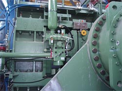
Roller press |
Ground level storage |
|
|
|
|
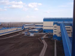
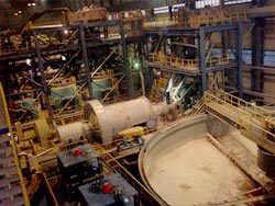
Vasilkovsky Mining and Concentration Complex industrial territory |
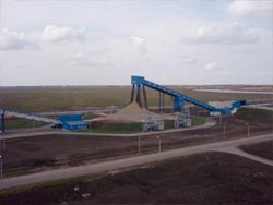
Crushing station |
|
|
|
|
Centrifugal bead mill |
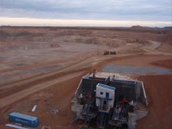
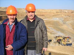
Open pit |
|
|
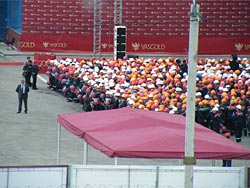
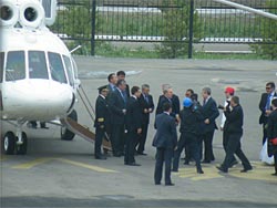
Opening ceremony |
President N. Nazarbaev at the opening ceremony |
|
|
|